What is BIM?
Published Date
Last Modified

Introduction to What is BIM?
BIM of Building Information Modeling has become a buzzword today in the Building Industry.BIM is also one of the most misunderstood terms. Many people interpret BIM as software. Many look at it with scepticism or apprehension. Many of us, still do not understand, how BIM is used, where all BIM is applicable, and who should be using BIM. Is it worth my while to look into BIM?
In this series of posts, I will attempt to clear the mist over BIM. I will try to address the questions that many of us have in our minds. I’ll explore the definition of BIM, and how it is being used. What type and size of projects can utilize BIM? What are BIM’s advantages and limitations, and what is the future?
Definition of BIM
NBS defines BIM or Building Information Modeling as “… a digital representation of physical and functional characteristics of a facility. As such, it serves as a shared knowledge resource for information about a facility, forming a reliable basis for decisions during its life cycle from inception onward.”
What is BIM? In simple terms, the Intelligent 3D Model, such as Revit embeds Graphical as well as non-graphical information that becomes available throughout the building lifecycle. This information can help with informed decision-making.
The embedded information includes, though is not limited to the following:
- Geometrical Information in terms of size and shape, colour and physical location
- Cost of Materials and Assemblies
- Thermal Performance
- Time and assembly of the elements that may take.
- Lifecycle or replacement time
As we see from the above, BIM includes a whole lot of information, that goes beyond the traditional dimensional information to include information that helps in analysis of Building performance as well as maintenance of a facility.
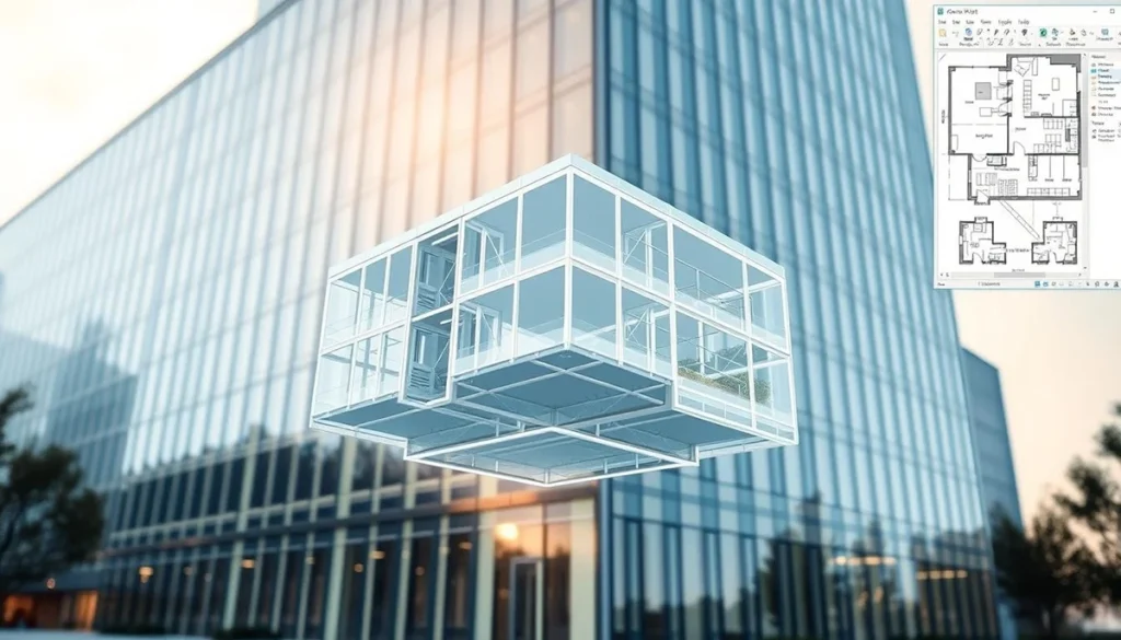
A core component of the BIM Process is a 3D Intelligent Building Model. The intelligent Building Model can store information needed for the BIM Process. Being an Intelligent 3D Model, it aids precise communication with the ability to bring together all the stakeholders on the same page.
What is BIM? BIM. The 3D Model together with a well-defined collaborative process form the BIM Process.
Uses of BIM
- The Collaborative BIM Process and the Virtual Building Model can be used for the following:
Document Exchange - Reviews and Quality Check
- Design Coordination
- Model Coordination
- Accurate Material Takeoffs and Bill-of-Quantities (BOQ) can be extracted from the Virtual Building Model
- Clash Detection between building elements such as Walls, Columns, Beams, Ducts and Pipes and so on.
- 5D Construction Planning (3D + Cost and Time)
- Daylight Studies and Green Building Analysis
- Design Documentation
- Planning Construction and Post Construction Facility Management
Benefits of BIM
Broadly speaking. BIM helps cut down costs of Construction, minimize clashes between building elements and ensure Projects get delivered on time. Building projects are a collaboration between the project promoter, the Design team and the Construction team. BIM defines this collaborative process and provides tools for effective collaboration.
The BIM Process
BIM generates graphical and non-graphical information termed as Data Sets. Typically, the BIM Process begins with (EIR) Employer’s Information Requirements. The EIR defines the Employer or Project owner’s expectations from BIM, the kind of information required from a vendor or supplier. This document formulates the Employer’s or Project owner’s objectives of BIM.
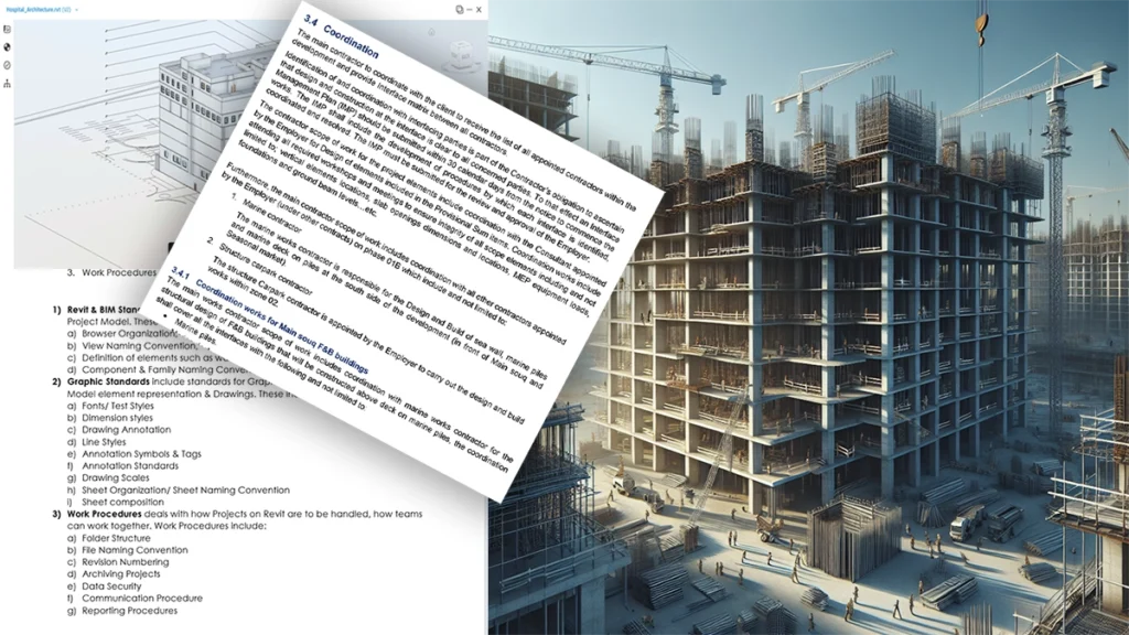
BIM Consultants develop BIM Execution Plan (BEP) based on EIR. BEP defines:
- The collaborative process,
- BIM Production Standards.
- LOD Levels required.
- Milestones and deliverables for each Milestone
- Review Process and Cycle
BEP or BIM Execution Plan forms a legal document for a project.
Why do we need BIM?
Let us try to understand the need for BIM and why has it become so important.
Not so long ago, and even in many of the current situations, there is a disconnect between a Project Promoter, Architect, Engineering Consultants, and Contractors. Each one visualizes what is to be built differently. As a result, there is a shortfall in expectations, decisions could go wrong, costs rise, and there are construction delays.
This happens because of multiple reasons. Amongst these the following stand out:
Improper and ill-defined Communication between stakeholders at all stages of a project.
- Project Expectations and outcomes are not clearly defined.
- Lack of Pre-Construction Coordination
- Mixed up 2D CAD Drawings and 3D Revit Models
- Ill-Defined Document Production Standards
This lack of coordination and inadequate pre-planning often results in almost every stakeholder losing. BIM tries to resolve these very issues.
Understanding LOD
The level of Development is a specification that defines the level of information for each stage of a project. The basic specifications were developed by the AIA (American Institute of Architects). LOD specifications form one of the essential parts of the BIM Execution Plan (BEP).
The level of Development is the amount of information that goes into a BIM Model. Level of Development defines the level of design decisions that have been taken regarding a facility. This may be related to typical design stages of a Project:
- Pre-Design
- Schematic
- Design Development
- Permit
- BID/ Tender
- Construction Drawings/ GFC
- Construction
- As-Built
- Facility Management
The level of design Decisions or the amount of information about a project increases with each stage. The use or objectives of this information too changes with each of the stages. For example, at Pre-Design stage the information available is architectural Program requirements and Site information, Built up area and the total Coverage available.
Here is a list of LOD Specifications as per BIM Forum:
LOD 100:
LOD 100 elements are not necessarily geometric representations. Examples are information attached to other model elements: symbols showing the existence of a component but not its shape, size, or precise location; or space reservation volumes. In essence, if information about an element can be derived from the model but the element is not at LOD 200 it is said to be at LOD 100. Any information derived from LOD 100 elements must be considered approximate.
LOD 200:
LOD 200 elements are generic placeholders but are recognizable as the components they represent (e.g. a pump, a light fixture, a beam, etc.). Any information derived from LOD 200 elements must be considered approximate.
LOD 300
LOD 300 elements are sufficiently developed to fully convey the design intent for the represented item. Note that while neither the LOD definitions nor this Specification specify who models the element, designers rarely generate model elements higher than 300. See interpretation of LOD 350 below.
LOD 350
LOD 350 is intended to define requirements for model elements that are sufficiently developed to support construction-level coordination. This LOD usually requires craft knowledge, thus the caveat in the LOD 300 interpretation above that designers rarely generate elements at LODs higher than 300. It should be remembered, though, that neither the LOD definitions nor this Specification specify who models the element – if a design team has craft knowledge available, they might choose to develop elements to LOD 350 or higher.
LOD 400
LOD 400 describes a model element developed to the level of shop drawings – in most cases, if a project’s specifications call for shop drawings of an item, the project team might model the item at LOD 400. Thus, most models contain few LOD 400 elements.
LOD 500
LOD 500 does not indicate a higher level than LOD 400, rather it indicates that the element’s geometry is determined through observation of an existing item rather than design of a future item. The LOD 500 definition requires that the model element’s accuracy be specified – BIMForum recommends USIBD’s Level of Accuracy (LOA) Specification for this purpose.
BIM Dimensions
BIM Can be utilized for the entire lifecycle of a construction project. Each of these stages requires information specific to a stage. BIM Dimensions defines these. BIM Dimensions typically define the information that is required to be modelled.
2D BIM
2D BIM Model has X and Y axis, typical of legacy CAD Systems, including early versions of AutoCAD.
3D BIM
3D BIM constitutes X, Y and Z dimensions. Typical Revit Models are 3D BIM. These 3D BIM Models can be used to generate 2D views such as Plans, Sections, Elevations from the 3D Model. In addition, Schedules and Quantity Takeoffs can be generated from the 3D Model. Multiple Models from other disciplines can be used to perform interference check.
4D BIM
4D BIM adds Time information and Construction Sequencing. 4D BIM is typically carried out in software such as Autodesk Navisworks.
5D BIM
5D BIM adds cost to the BIM Model (4D = Time, 5D adds Cost). 5D represents how costs relates to Time.
6D BIM
6D BIM adds Facility Mangement dimension to BIM. Models are specifically created for Facility Management.
7D BIM
7D BIM adds Sustainability information to the BIM Model.
8D BIM
8D BIM adds health and Safety information.